How Intakes Work
There is a lot of misinformation on how intakes work to increase horsepower on automotive engines. In this article, we will work to explain the engineering behind intakes and demonstrate how our intake designs increase horsepower for your vehicle.
Our intakes are produced using state of the art methods from start to end.
- 3d scanned stock airboxes to ensure fitment and maf calibration is perfect
- CFD to ensure the flow was optimized and nothing left on the table
- 3d printed to check fitment, flow testing, dyno testing
- CNC carbon fiber molds
- Autoclave carbon fiber production ensuring longevity and structural integrity
Using the F1x as our example, the testing is focused more on durability and heat soak, than horsepower numbers.
I’m sure you’ve heard that intakes make power, but that’s not the whole truth.. Bolt on intakes FREE up power. The engine is already producing what it can output at a specified RON (gasoline) knock limit provided a chain of other criteria are not holding it back. As an OEM (RK’s design engineer has worked for an OEM) we design intakes very differently than the aftermarket. We have noise, vibration, power constraints, costs, and durability in mind. A combination of these constraints are why OEM manufacturers leave “power” on the table. In the aftermarket the consumers are primarily power and aesthetics driven, so we can optimize for those and not other constraints.
Given that the intake system is purposely constrained from factory. The ECU is calibrated with the designed intake system and it’s sold to consumers.
So how do you “free” up this power?
The common assumption is that your intakes make power. False. The governing equation/theory behind this is: BMEP = IMEP + PMEP + FMEP. Where BMEP is the brake power (horsepower produced at the crankshaft output). IMEP is the indicated mean effective pressure as indicated in the power loop of the PV diagram. This is where the magic happens, IMEP is the the maximum energy produced via combustion in the engine. PMEP is where the intakes come in. PMEP is the pumping mean effective pressure. The engine has to utilize some of its IMEP to suck in the air and push the air out, this isn’t free after-all. Then you have FMEP, the friction portion of the game, this is your rotating assembly, lubrication, seals, and etc.
Here’s a PV diagram to visualize what’s going on.
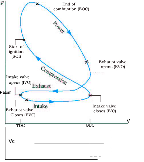
BMEP = crank power = measured using a dyno
IMEP = power loop = measured using in cylinder pressure transducers
PMEP = pumping loop = measured using in cylinder pressure transducers
FMEP = friction = calculated using math by knowing BMEP/IMEP/PMEP
So now that we’ve established power is only made in the power loop, everyone should be onboard with why intakes don’t make power.
Intakes are like straws, we as humans can suck in x amount of water using a straw that is half an inch wide, we can also suck x amount of water with a straw that is 4x as wide. It’s easier to drink through the bigger straw right? Same concept with an intake! An efficient intake is like a big straw: really easy to suck the water through. This value, “delta pressure”, is the amount of suction needed to move a certain amount of fluid through a vessel.
We want to make it easy for the engine to “breath” on a forced induction application, easier for the engine to breath means less power it has to use to suck that air. See where this is going?
Let’s put some numbers with our equations:
BMEP = IMEP + PMEP + FMEP
(+) = (+) + (-) + (-)
(end power) = (total power) + (pumping loss) + (friction loss)
BMEP = IMEP + PMEP + FMEP
10 = 14 + (-2) + (-2)
That is configuration A
now we have our new intake, configuration B, the big straw
BMEP = IMEP + PMEP + FMEP
11 = 14 + (-1) + (-2)
You just increased the crank power of the engine, by freeing up power that was always there! This is why when you see flow in LPS, it doesn’t hold much value, so you increased the flow? Does it mean anything, because the flow has to have some type of delta pressure associated with it. How much suction did you need to produce that flow? I can take a 2″ pipe and flow 500 LPS through it, but I need to have a substantial amount of suction on it. My 3″ pipe only flowed 300 LPS, but it was much easier to suck through. Marketing will make you think the 500 LPS is better because well…you didn’t know, now you do!
We can now demonstrate why our intakes will produce an increase in power
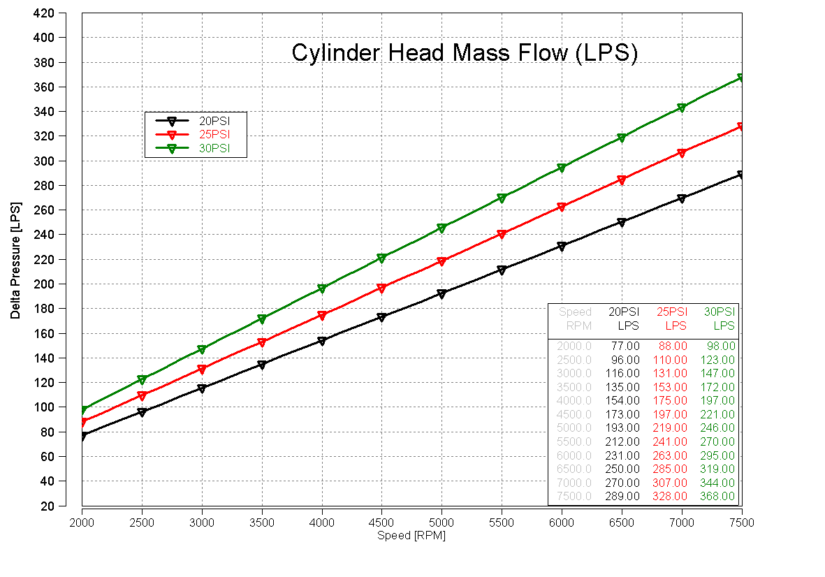
This graph shows the amount of air an engine is consuming based on boost pressure (turbo application only). This gives you an idea of how much air your engine is consuming at wide open throttle at a certain RPM.
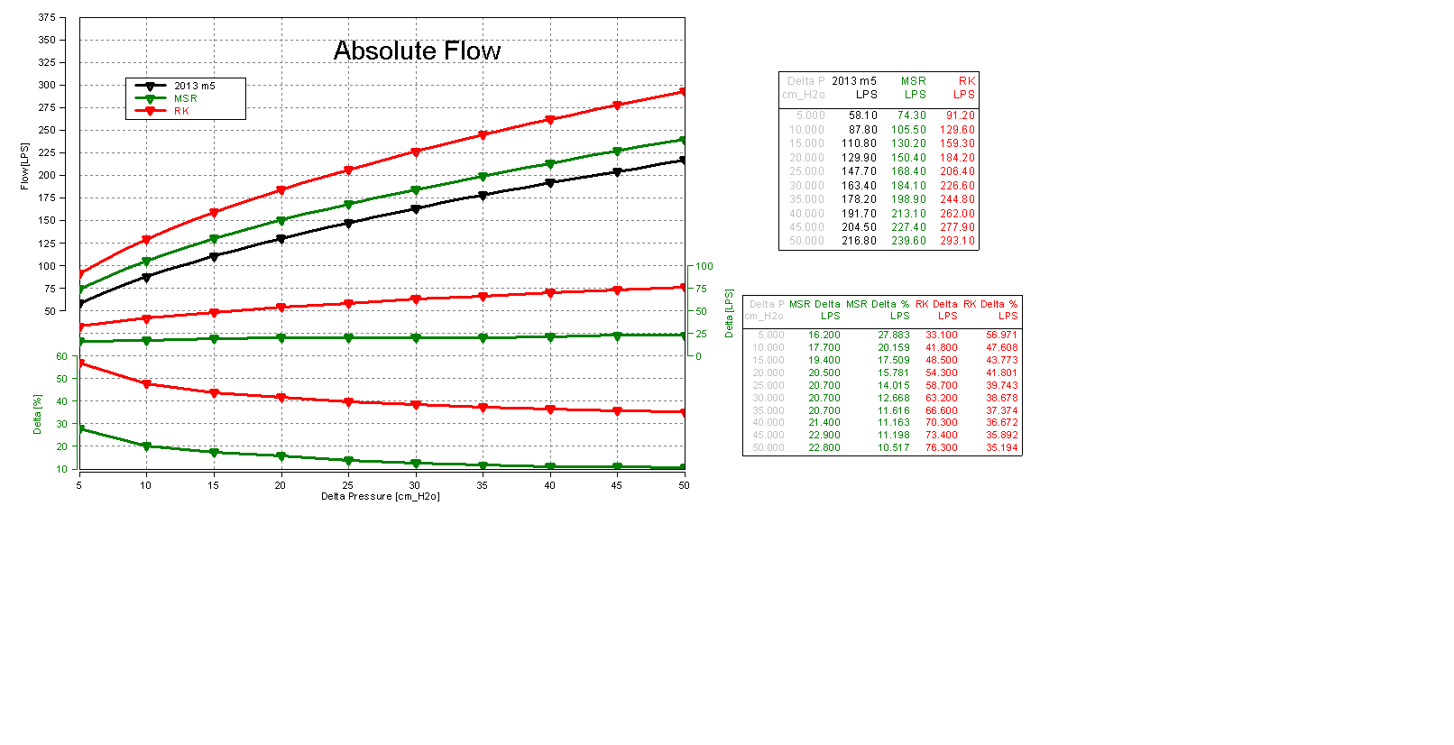
Next is the typical “flow increase” diagram. The X axis is a function of delta pressure, which is how results should be stated. But as we discussed earlier, this doesn’t help quantify why engine is making power. You see increased flow at each delta pressure, but it doesn’t show what the delta pressure drop is, just what you increased flow by.
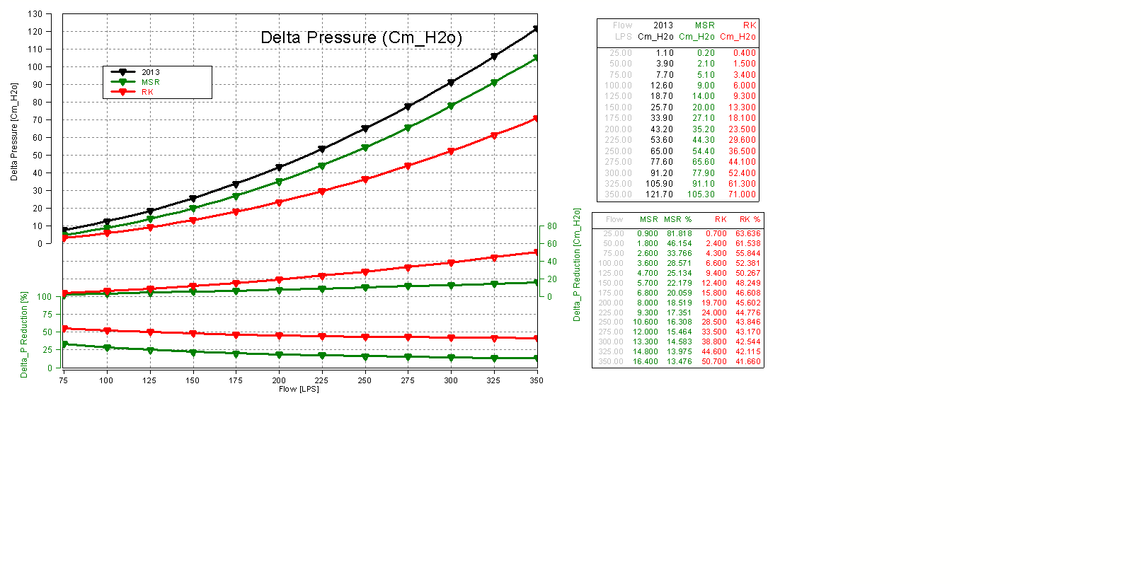
This is why you should ask the vendor for this graph. A chart of delta pressure as a function of flow. Now you can quantify what benefits to expect based off the chart below. You can reference to the cylinder head flow chart and compare what delta pressure benefit you have based off the RPM at WOT condition. You can see below how our intakes compare to a competitor and how they compare to stock. We’ve reduced your pumping loss from 40-60%, power you were allocating to move the air into the engine before is now being used to move your car!
The reason to bring this up is because it’s really easy to quantify the difference between intakes when conducting testing using a flow bench. It’s not easy to compare intakes or really quantify power on a chassis dyno because there is so much going on that needs to be factored in. You need a bench dyno running some state of the art equipment to truly quantify it, typical of OEM style testing. The flow bench is something anyone who’s charging several hundreds of dollars for an intake should use to validate their product. You can go full circle and derive a correlation between delta_P reduction and the pumping loss benefit if you had a system sophisticated enough to accurately capture the PMEP inside the engine. Then you could back out the increase in power as a function of Delta_P. You’ll be hard pressed to find shops outside the OEM that have this capability, we know of only a handful. Happy modding!
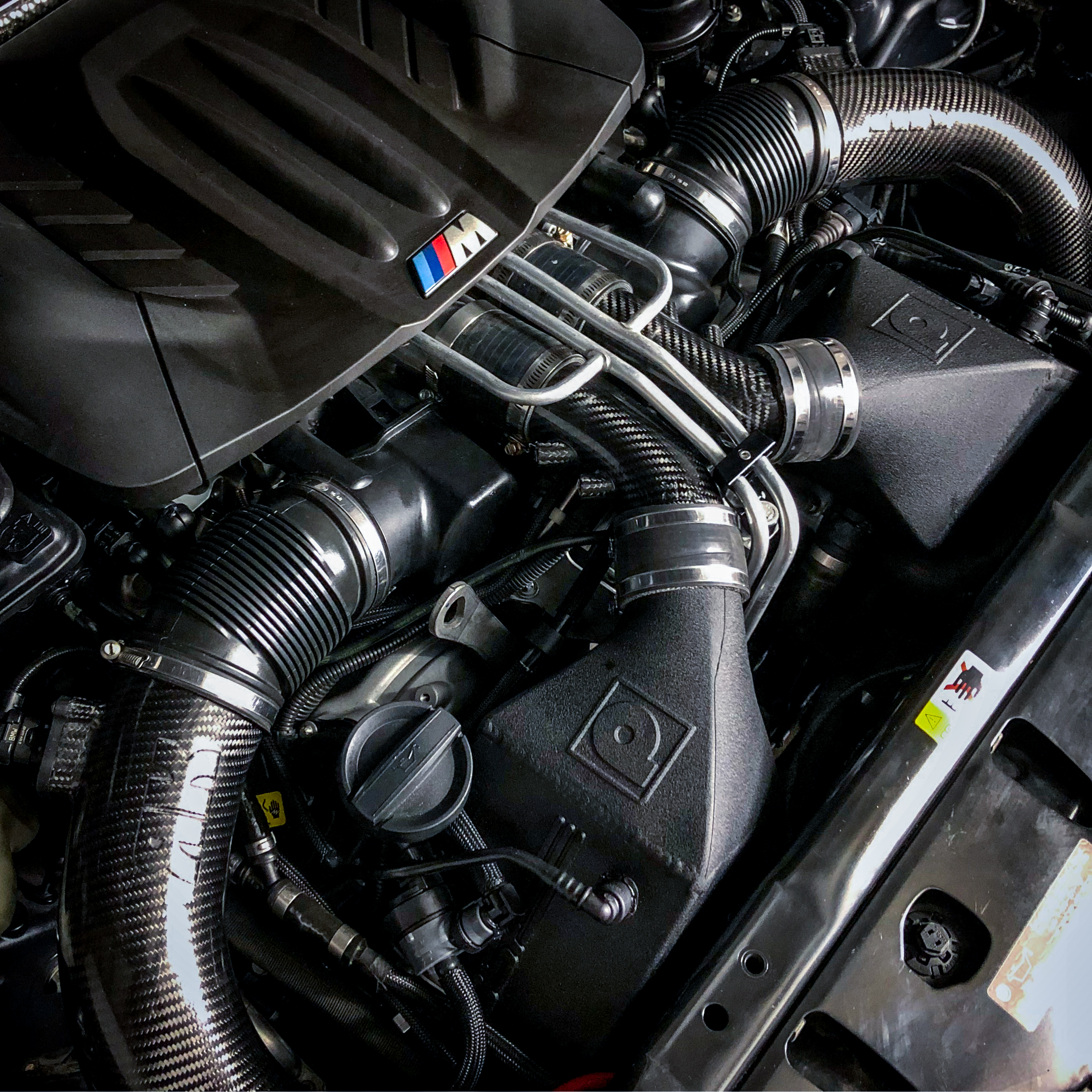
Here are the pics that make everything all worthwhile:
PS: Many assumptions were made to simplify this analysis. We would be more than happy to explain in more detail for anyone interested in that type of discussion..